What is Entity Relationship Diagram ?
Entity relationship diagram (ERD) is a data representation format that often used on software engineering project to describe data structure for a table based RDBMS (relational database management system).
Imagine a table consist on excel file of list of student name who attend math class along side with their first name, middle name, last name, class and age as the column Those data representation are called as entity table.
ERD take those table and **correlate with one or more table** to create meaningful business context.
For example, a table that consist of student information combined with a table consist of class information could be a business information regarding class assignment.
Another example is correlation between table consist of user list with table that consist of their goal along side with target date could be a business information about five years career plan.
Conceptual vs Logical ERD (Entity relationship database)
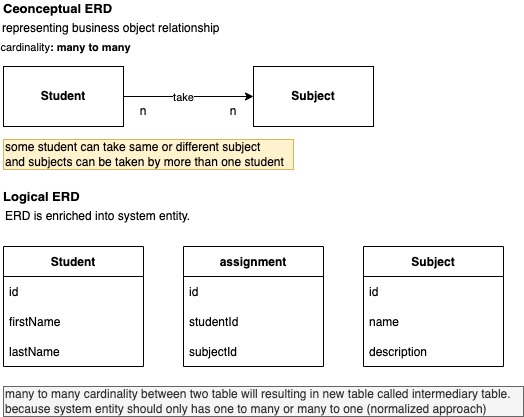
Conceptual ERD and logical ERD serve different purposes. Conceptual ERD is representing how each of the table (or also often called as entity) is correlated without knowing the column details to create high level business context that still have multiple interpretation.
Logical ERD is the enrichment of conceptual ERD by giving detailed parameter/column to each table in order to add scope/boundary to the business context so ensure non ambiguous information (single interpretation).
Apart from the objective differences, both conceptual and logical ERD require different pre-requisites before it can be drawn.
Conceptual ERD is typically created once the high level requirement has been defined and usually in form of user story or functional requirement.
Logical ERD will be drafted when the user story details has been created as it consist neccesary process and technology information including following item:
- process within the user story (how to the user/persona will execute the story)
- non functional aspect such as the technology enabler for the user story (for example on user login user story, the user story details must specify the authentication method such as gmail authentication using firebase or appleid authentication or custom username and password via JWT)
Comparison Between Conceptual vs Logical ERD
below are the comparison of conceptual ERD with logical ERD based on several angle
| Characteristics | Conceptual ERD | Logical ERD |
|---|---|---|
| Definition | Correlation between one or more table to create a business context | Table contextualization from the ERD |
| Purposes/Objectives | Identify persona, activity or object that potentially be part of specific process | To identify specific use cases within process |
| Level of Representation | Strategic | Tactical |
| SDLC Phase | Requirement gathering with business user | Drafting functional requirement document (FRD) |
| User | Business User & Business analyst | Business Analyst & Solution Architect |
| Mindset (When drawing) | Business & Process Oriented | Process & System Oriented |
Skipping Conceptual ERD and Directly create Logical ERD
— logical ERD can only be created once conceptual ERD has been agreed.
By Skipping conceptual ERD and create the logical ERD immediately will risk the system to not met with business user requirement as the strategical analysis is bypassed.
Strategical analysis in context of ERD creation is a process to align the goal of organization and related business user.
While, operational analysis (in same context, ERD creation) is to define how to translate organizatin and business user objective into software system design.
Hence, jumping immediately to logical ERD without the conceptual ERD will definitely cause system misfit during the rollout/go live. Ended up with business user or top management complaining about the software quality.
At worse case, the misfit software will become an artifact that no one will used.
Steps to convert conceptual ERD into logical ERD
below are the first step to draw logical ERD based on pre-existings conceptual ERD.
- Pre-requisite checking
- Identify technology related element (NFR) requirement and enrich to the user story details
- Draw the logical ERD
- On the logical ERD design, it is only required to specify the table attribute/column, foreign key and the relationship/table cardinality.
- Attribute’s data type, referential integrity, indexes , primary key will only need to be defined during the physical ERD design.
Note that both of conceptual and logical ERD are drawn by solution architect (SA) or a devlead in some cases. The responsibility is not lies under BA.
Pre-requisite checking
At this stages, SA should sit with their counterpart business analyst to check following things:
- User story definition is clear (non ambigious). Ideally the persona is firmed and has specific target goal.
- User story details consist of both process related and mentioning the neccesary technology choice or consideration information
- (hardest part) Brainstorm about the conceptual ERD, challenge the BA whether the listed entity and its relationship are matched with organization or business user objective / purposes.
- (optional) - Ensure the wireframe are defined and has been agreed between the BA and business user.
note that, some project might run without UI/UX at the design stages. It all downs back to the project manager/solution architect preferences
UI/UX wireframe can be a great helps to understand business user requirement and make the logical ERD will be easier to craft as the column and information details is avaialble on the wireframe.
Howver, if the user story is detailed enough, the neccesary column and information can also be extracted solely from the user story itself.
— hence, it all down to the project preferences.
ERD first or Wireframe First ?
below are the typical practices to determine which one is first (ERD or wireframe)
- Backend focused project such as core banking, ERP, analytics will focus on writings all details in form of functional design/user story as the project need to be focused on more building lean and optimize data structure
- Client facing project such as mobile banking, web based saas usually will have the wireframe createdf before ERD to ensure it has the best user experiences as the project is meant to attract more potential user or customer and drive the sales/leads.
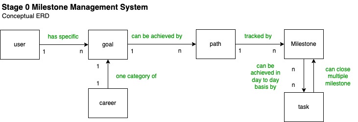
Current Conceptual ERD
below is the current conceptual ERD from previous iteration for milestoneku (SaaS product to manage personal milestone)
 Current Conceptual Entity Relationship Diagram
Add related technology requirement / non functional requirement to per entity
Below is the conceptual ERD that was previously created and agreed for milestoneku (milestone management system) product.
Add technology related requirement that might affect the logical ERD which derrived from the user story details as well as from the SA’s interpretation and the architecture strategy for each entity
note: not all NFR will affect the database schema, its important to only identify potential NFR that could alter the database model.
| Entity | Non Functional Requirement |
|---|---|
| a | b |
note: Ideally, these NFR also added on the user story acceptance criteria as well. In some project, the user story details will be updated by the SA when they create the logical ERD as this is the stages where business process and technology requirement are combined.
Apply Business Rule From 1NF up to 4NF
Apart from incorporating NFR (non functional requirement) to the logical ERD alongside with the user story acceptance criteria (AC), normalization business rules are also need to be factored out when designing the logical ERD.
Below are the normalization rules from 1NF to 3NF that suppose to be sufficient for most software engineering database design.
- 1NF Rule: Ensure no multi valued attribute/column/parameter on all table.
On most cases, 3NF normalized table is usually enough unless the data model consist of following scenario that require BCNFF and 4NF
- Require BCNF if only if there is one or more non determinant on each of the FD (functional dependency) that not part of the super key/candidate key/primary key. Note: for example, the A->B functional dependency notation, A is the determinant and B is the dependent. A (determinant) must be primary key/super key/candidate key.
- Require 4NF if only if MVD (multi valued dependency) is found during the design process - if there are more than one non key attribute and each of the non key attribute are not dependent on each other.
for the complete step by step to execute 1NF to 4NF normalization, check following links below
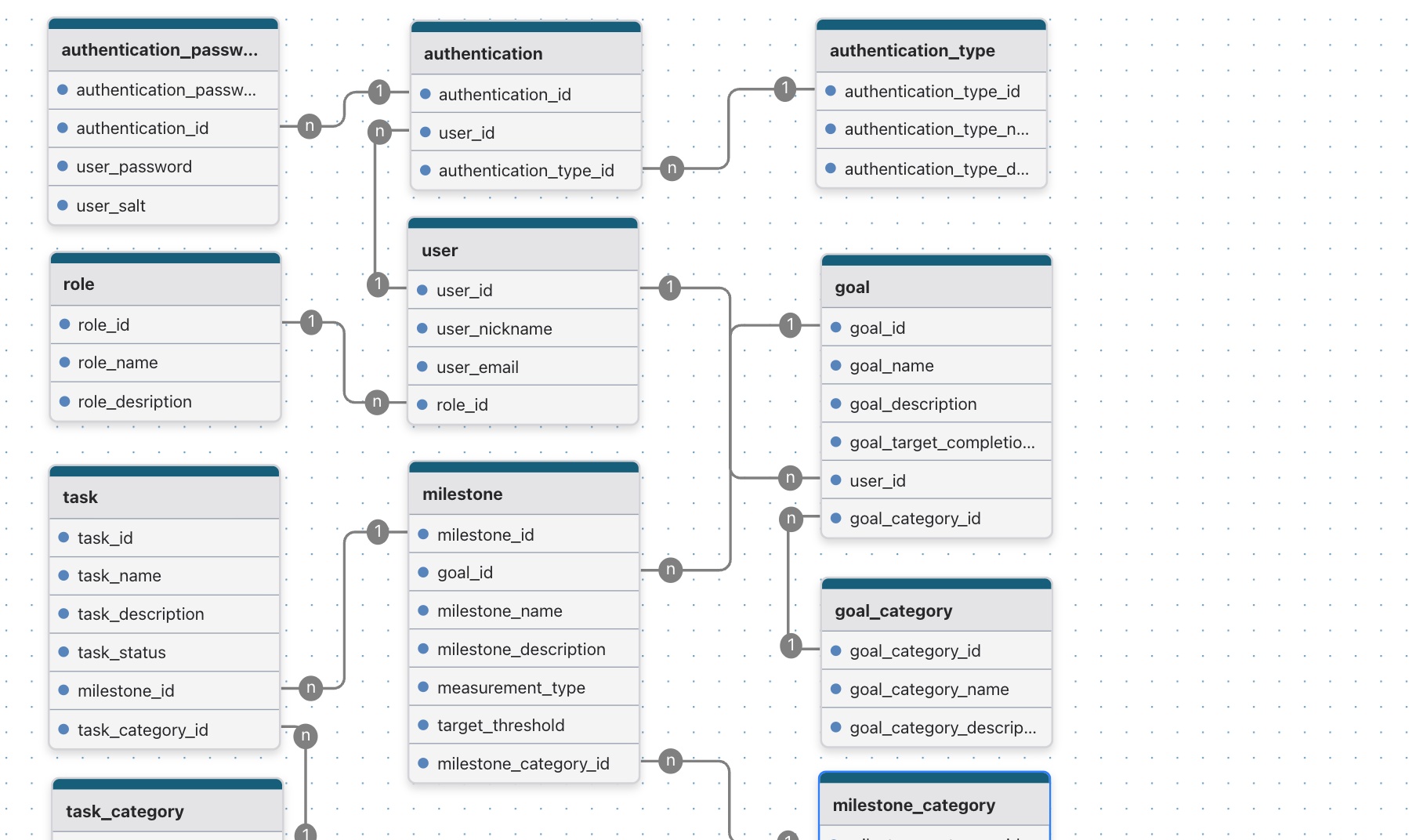
Final Logical ERD
Below is the final logical ERD for milestoneku by considering acceptance criteria user story, identified NFR as well as the normalization guideline.
 Current Conceptual Entity Relationship Diagram
Note: FK (foreign key) and also the data type will be included later on during the physical ERD design.
— Thought process behind the design:
- Users can have multiple authentication type (1. firebase/gmail auth 2. classic username-password)
- User has role
- Role is represented in different table for future use when developing the role based access control or often called as user permission to access specific feature/module/api (depend on the granularity)
- Authentication_password will be used to store the hashed password as well as the specific salt (to encoforce more secure security)
- Users can have many goal (goal->user)
- Goals can have many milestone (milestone->goal)
- Milestones can have many task (task->milestone)
- milestone progress will be tracked dependning on the measurement_type (1. task based, say if all the referenced task are completed means the milestone is achieved 2. manually input by user, for future development)
- Milestone has a threshold
- eac of Goal/milestone/task has their own category, hence user can categorize or group their goal/milestone/task based on the characteristics.
